|
|
| Place of Origin | Shenzhen, China. |
| Brand Name | SINOMATIC |
| Certification | CE/ ISO |
| Model Number | SN-BG102 |
Die-Casting Aluminum Alloy Motor Double Sensor Vehicle Entrance Automatic Barrier Systems
PRODUCT SPECIFICATION
| ITEM | SPECIFICATION |
| Model No. | SN-BG102 |
| Boom length | 1m to 6m |
| Opening/Closing time | 1s, 1.8s, 3s,6s |
| Supply voltage | 110V AC or 220V AC |
| Working current | 1.3A(110V)/ 2.7A(220V) |
| Power consumption max. | 120W |
| Frequency | 50~60Hz |
| Cabinet material | Powder coated steel |
| Boom material | Aluminum alloy |
| Temperature range | -20℃~+60℃ |
| Humidity range | ≤90% |
| Housing dimensions | (W x D x H) 328*286*934(mm) |
| Packing dimensions | (W x D x H) 460*420*1150(mm) |
| Net weight (without boom) | 55Kg |
| Gross weight (without boom) | 60Kg |
ABOUT MODEL BG102 BARRIER GATE
BG102 series parking barrier adopts die-casting aluminum alloy motor and extraordinary structural design,
it offers not only a long-life cycle, high reliablity and quality, but also reduces the difficulty of equipment maintenance.
It is an ideal choice for vehicle entrance control management.
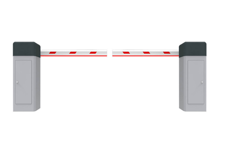
PRODUCT DIRECTION
![]()
PRODUCT PICTURE
![]()
Functions & Features
1) Manual realease
2) Machine core with compression spring, effectively avoids the accidents caused by spring breaking;
3) Die-casting aluminum alloy motor, precision and good at thermal radiating;
4) Motor cooling fan, solving the problem of heat-protection;
5) Double safety limitswitches (photoelectricity limit switch/motor memory sensor);
6) Reversing on obstacle;
7) Auto-closing;
8) Support the In frared Photocell for anti-bumping function(optional);
9) Support the external and internal Vehicle Loop Detector;
10) Traffic light interface;
11) Wire Control ( switch signal) / remote control (418 HZ/433 HZ );
12) RS485 Communication module (optional).
INSTALLATION STEPS
1. Installation precautions
1) Install the parking barrier on a level ground. If the ground is not solid and level, a cement base is needed before installation.
2) The boom can be cut, but cannot be increased. After cutting the boom length, the spring balance needs to be set again to achieve balance. Two plastic nuts lie in the bottom of the spring is designed for adjusting balance.
3) Do not change the wire connection inside when power on.
4) The GND should be connected to the cabinet for secure protection.
2. Cable embedding
1) Prepare φ25 protective sleeve and cable in advance.
2) Route cables to be connected through protective sleeves.
3) Use a tool to open a cable tray on the ground, see Figure 2-1.
3. Cabinet installation
Installation Procedure
1) Use screw pad to mark the installation position of the cabinet.
2) Drive four expansion bolts into the bolt holes, as shown in Figure 2-2.
3) Install screw pads and use a wrench to tighten nuts, as shown in Figure 2-3.
4. System diagram
Installation Diagram for the Parking barrier and Wall.
The distance between the cabinet and the wall should be greater than or equal to 100 mm. The distance between the boom and the wall should be greater than or equal to 100 mm.
Case reference
![]()
CONTACT US AT ANY TIME